DMV Display

For this project we had to create a circuit that would display the numbers from 0 to 80. The circuit had to pause and be manually reset once it got to 80.
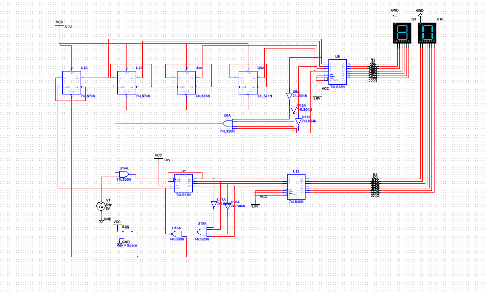
This is the circuit I created in regular multisim mode that counts from 0 to 80
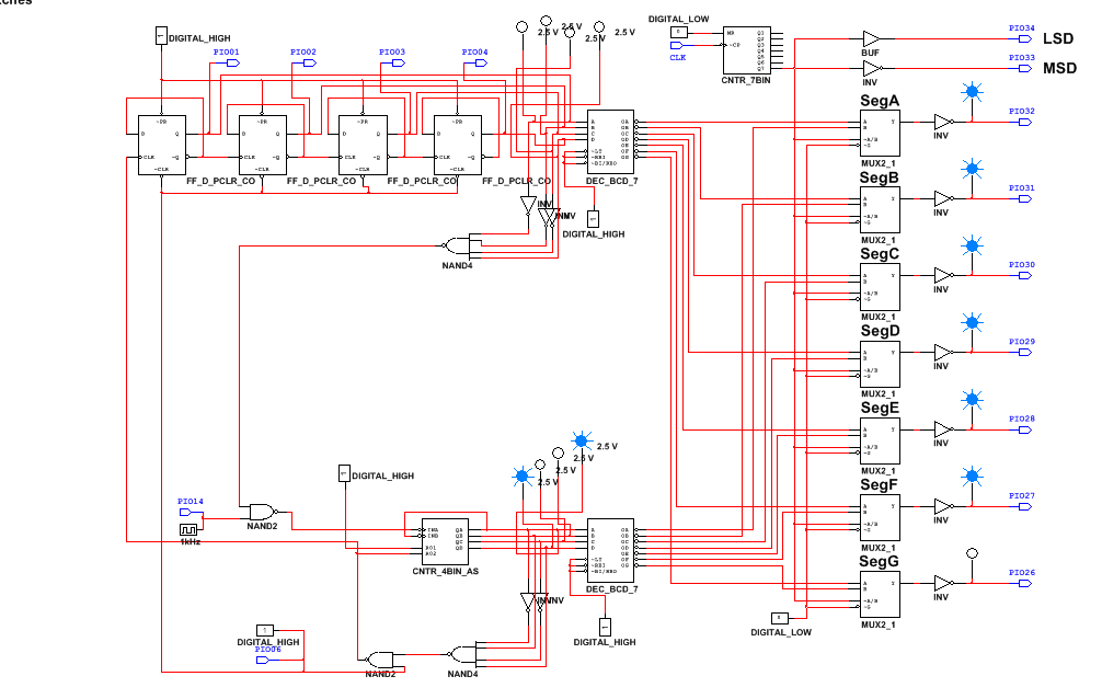
This is the circuit I created on the PLD mode that was used to display the 0-80 on the breadboard.
The difference
The difference between design mode and the PLD mod is the ability of the PLD mod to upload it to a breadboard to display the numbers, design mode can not be uploaded to a breadboard. Also they have the same components but they different names. PLD mod also gives you the ability to use inputs and outputs.
Bills of materials
CMOD - 1
Breadboard - 1
Companion - 1
Wires - A lot
Breadboard - 1
Companion - 1
Wires - A lot

This is the wiring that I did on the breadboard to get the display to work.
Final Project Conclusions
The difference between the SSI and the MSI circuit is that they have different amount of gates. SSI has less than 10 gates and MSI has anywhere from 10 to 100 gates. The limitations of MSI circuits that I created was that it could only count up and lacked the ability to go back a number in a situation where you accidentally hit a button. The ripple effect happens in asynchronous counters when the next gate is waiting on the signal from the clock to go through previous gate. Some of my classmates used a demultiplexer so they would be able to use a 7 input display instead of just using the 4 input hex display.
