This program was used to simulate a majority vote circuit that met the design principles. We were given scenarios of how the president, vice president, secretary, and treasurer would vote and what the outcome ruling would be. With that information we figured out that any three votes would win, the president and one of the other three votes would win, and all of their votes together would also win. For the whole project we could only use 2 input AND and OR gates to create the un-simplified and simplified circuits.
Truth Table

|
This is the truth table that I created to show all the different possible outcomes. Due to there being 4 columns there has to be 16 rows. Each variable stands for a certain position. P stands for President, V stands for Vice President, S stands for Secretary and T stands for Treasurer. The D stands for the decision on if the law gets passed or not, the 1's mean that it would be passed and the 0's mean that it would not be passed. The 1's and 0's in the other four columns stand for if that person voted a yes or no, 1's mean yes and 0's mean no.
The un-simplified expression is in SOP (sum or products) form because it is the easiest form to get from the truth table. Each midterm can be found on the table. I looked for which products resulted in a 1 (the vote passing) and put that into the expression. The line above the variable indicates that it is inverted, which means the variable is not on. |
Un-simplified Circuit

|
This is my un-simplified circuit and it is composed of one 5 volt power source and a ground. My four inputs are P, V, S, and T and they are connected to the 5 volt power source and ground. These inputs are connected to NOT gates to make them inverted. of needed. I then used 24 AND gates to multiple all the different inputs together. Then I used 7 OR gates to add all the combinations together to get my final answers. There is a total of 34 gates which shows how expensive it would be to build the un-simplified circuit.
|
Boolean algebra

|
This was the boolean algebra that I used to simplify the expression. The Boolean algebra made making the simplified expression much easier and building the real circuit on the bread board much easier as well.
|
Simplified Circuit

|
This is my simplified circuit. This one is much neater and easier to follow then the un-simplified circuit. I did not used bus form. The purpose of the resistor before the LED is to join all of the minterms together. I used 5 AND gates and 3 OR gates. I would need two 08 chips and one 32 chip. I figured this out because each chip has 4 gates, so for 5 AND gates you would need two and for 3 OR gates you would need one.
The simplified circuit required less gates. It required 4 less inverters, 19 less AND gates, and 4 less OR gates. It contained the same amount of chips though. This is important because it saves time, money, and materials. Also if you tried to create the un-simplified circuit the would be a much higher chance of doing something wrong and would be very hard to find the mistake compared to making the simplified circuit. The simplified circuit is just much easier to understand and build. |
Bills of Materials

|
The table to the left shows the materials I used for my circuit. We were only able to use 2-input gates. Therefore, I used a total of 3 gates for the circuit. I also used one breadboard, one breadboard companion and a lot of wires.
|
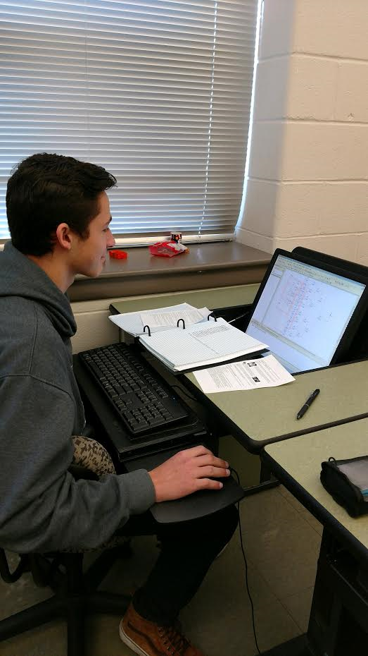
Bread-Boarding

Beginning to building the circuit.
|

Midway between building the circuit.
|

End of building circuit.
|
My bread boarding experience turned out to be pretty fun as I learned how to make the circuit properly. At first it was a little confusing but my teacher, Mrs. Zienty showed use the basic information we needed t know and helped use through the way if it was needed. After I got a better understanding of how to create the circuit everything went smoothly and I finished my working circuit. Some mistakes I made was putting the wires in the wrong rows and putting the wires in the wrong location of the chip. I used troubleshooting to make sure I was putting wires in the correct spots but besides that I didn't need to do mush troubleshooting since mine worked the first time.
Conclusion
This project had many important take-aways such as troubleshooting. I learned that it is very important for not this project, but in almost every project that I do. Another important take-away is that organizing things can make many projects easier. I didn't organize my circuit but I saw some other classmate's circuits that were organized by color coding the wires, I found it very helpful to locate any mistakes and keep your breadboard neat and it was much easier to understand the circuit. In this project the smallest details can mess up your whole project, this is why trouble shooting and organizing is key with in this project and my other projects. In Multisim and in real life while bread-boarding, if one wire that is not connected to the right spot it can cause the whole circuit to create the wrong outputs. When going from a problem statement to a finished circuit you first want to make a truth table. Then you want to make and simplify the logic expression and then with the simplified expression you want to make the virtual model on Multisim. Finally, you want to create the circuit on the breadboard in real life. Boolean algebra is useful because it allows a person to simplify their logic expression so that they can make a easier circuit that is easier to understand and requires less material.
